
 |
|

Изготовление Back Lock от Neil Charity со вставкой из перламутра
Взято с knifenetwork.com
As a break from building liner-locks and because I bought some really nice gear at this Blade Show in Atlanta, I've decided to build an interframe. Also as a result of popular demand (Ha ha) I am going to post it on this forum for those who are interested. I don't propose to go thru the process of building the basic folder on this forum but this process I use to mill the cavities and fit the inlays.
I don't own a pantography so I've had to resort to using my mill-drill and the result I get is really amazing. I will show you my set up and the jig etc. I use and the rest is up to you. If you have any questions you will have to post them on the thread I have opened up and I will endeavour to do my best.
You will have to bear with me as I build this piece as the process is slow anyway and as I have to stop and photography each step that will slow the process down even more.
Figure 100 shows the drawing of the basic folder and my hardened steel (O1) template that I use as a drilling and profiling guide.
Figure 102 shows the 2 halves of the frame profiled and all holes drilled and reamed. Note that the bar pivot pin hole is not drill all the way thru., I have drilled in about .050".
Figure 101 shows all the parts of the folder laid out and I will now proceed the build the basic folder.
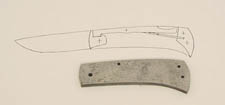
figure 100

figure 102

figure 101
Ok, I have built the basic folder with the blade profiled, bar fitted to it's almost finished state and it opens and closes OK.
Figure 104 shows it in it's open position and figure 103 in the closed position. Note that I have yet to grind the blade, I can do this as a break during the next stage.
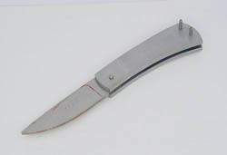
figure 104

figure 103
To build an interframe by whatever means you need a master to work from and designing the master is not difficult.
You need a piece of graph paper (I use metric as the squares are of smaller size than imperial) on which you place you template and trace the outline on the graph paper trying to keep the horizintal axis of the knife parallel to one of the axis of the graph paper. Take several photocopies of this to work from (this preserves your original), and draw the cavity or cavities that you wish to have, place a nice square around the drawing. You now take a photocopy of this or stick the drawing on a piece of ground steel ( mild steel will do), now place your template over this aligning it with the traced outline, clamp, drill and ream the blade pivot pin hole and the 2 spacer pin holes. Remove the template and drill, saw and file to the line that you have drawn to mark the cavity/cavities. Try and keep your edges square as much as possible, but if your like me and not the best filer on earth not to worry I'll show you how to square them up later.
Figure 105 shows 2 masters that I use, the one with 2 cavities has been hand cut and the master with the oval has been wire cut to give a prefect oval. I will be using this one for this knife.
Next step is to mark the cavity on the frame that is going to be cut. The reason for this will become clear in the next stage.
Figure 106 shows the oval scribed on each frame half.
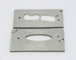
figure 105

figure 106
OK, I measure the thickness on the frame halves (in this case 3.45mm) then mount the 2 halves on my milling plate ( as shown in my previous tutorial on how to make a lock-back folder) then clamp the plate to the table of my mill/drill. Firstly with a 1/4" drill and secondly with a 1/4" endmill I drill/mill a hole to the depth I want my cavity to be. I like to leave "a wall" of about 1mm (.040") at bottom of the cavity so in this case I drill/mill to a depth of 2.45mm (.096"). The reason for doing this will become obvious as I progress.
NOTE: All my measurements are in mm. as my mill dials are metric.
Figure 107 shows the halves mounted on the plate on the table, the holes have been drilled and milled out.
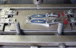
figure 107
I now proceed to set up my milling arrangement.
Figure 108 shows my milling "base", a piece of 800mm (8")x 300mm (12") x 12.5mm (1/2") surface ground mild steel plate into which I have inserted a steel collet with a 3/16' hole drilled in it. The piece of rod you can see in the picture is the follower, a length of 3/16" O1 drill rod that I have heat treated.
After clamping the "base" to my mill I put the follower in the chuck and with the hand wheels centre the follower over the hole in the collet. I then clamp both axis of the mill, zero the counters and remove the hand wheels. This now ensures that the milling cutter is centred over the follower.
Figure 109 shows the follower in the collet.
Figure 110 shows the follower in the collet and the cutter in the chuck in line with the follower.

figure 108
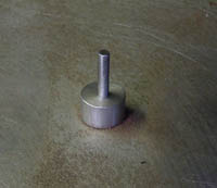
figure 109

figure 110
Figures 111 and 112 show the topside and underneath side of my milling "table". The table is made from surface ground mild steel measuring 6''x4"x1 1/4" with the legs being 4"x1"x1" and weighing 10.5 lb (approx. 5kg), the weight been the most important factor (the heavier the better). On the table are the locating holes for the frame and the master, these have been precision drilled all the way thru the table.

figure 111

figure 112
I now place and clamp one of the frame halves on top of the "table", locating its position with the pin holes and on the underneath side I locate the master making sure that I have it the correct side "up".
Figures 113 and 114 shows the master and frame half mounted on the "table".
I then place the "table" on the base ensuring that the follower is inside the cavity and with the milling cutter in the chuck I check that I have the master positioned correctly.
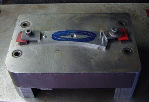
figure 113
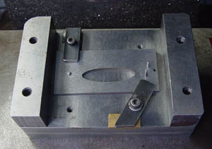
figure 114
I then zero the downfeed and lower the cutter .1mm (.004") into the hole I've milled in the centre of the cavity. This is a solid carbide end cutting burr and I run it flat out (2200 rpm) and use plenty of cutting oil.
Figure 115 shows everything correctly positioned and ready to go.
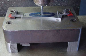
figure 115
IMPORTANT NOTE: When milling using this technique ALWAYS remove metal in a clockwise rotation and don't ever let go the table. The reason for the weight of the table now becomes obvious, because the "table" is not clamped but free standing it will want to "take off". This is the reason why I take very light cuts and always move clockwise to the hole milled in the cavity.
I now proceed to mill out the cavity.
Figure 116 shows milling underway and Figure 117 shows the first frame half completed.

figure 116
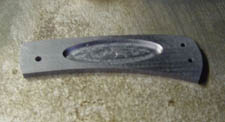
figure 117
Once the first frame half has been milled, replace it with the second half using the appropriate locating holes and on the underside of the table turn the master over, reclamp and mill out the second half.
Figure 118 shows both frame halves milled out. Occasionally I like to keep track on how long I spend on a task, helps me get a feel for the overall difficulty in making a particular knife, and on this occasion it took me 2 1/2 hours to mill out both cavities. When I first started making interframes it took me considerably longer.
When milling has been completed drill 2 small holes (1/16") in the floor of each cavity. This will enable the inlays to be removed and allow trapped air to escape.

figure 118
TIP: If you have hand filed the master the sides will be "off square" and need to be "trued" up. Figure 119 shows a new cutter with the end teeth visible, the other cutter is a worn cutter with the bottom ground flat and smooth. Simply mount the hand filed master on top of the "table" over a piece of stiff card, lower the modified cutter into the cavity and go round the edges carefully until the edges are "true", in other words use the burr as a motorized file. Be careful as carbide, although very hard, is very brittle.
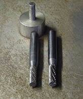
figure 119
The next step is to cast the master inlays from automotive body filler.
Because I can never align the cutter and the follower EXACTLY the same each time I set up and because all 3 jaw chucks have some runout (however minute) I cast my master inlays each time I make an interframe.
First off I apply a wax coating (either furniture wax or automotive wax) to the inside and outside of each frame and both sides of a flat piece of steel. Let it dry and rub off, the wax coating acts as a release agent for the body filler. Next I mix up some 2 part automotive body filler and fill each cavity with it, then clamp each frame to the flat piece of steel. It now becomes obvious why the 2 holes are drilled in the floor of each cavity as the excess body filler oozes out, wipe off this excess.
Figure 120 shows the frames clamped to the steel plate.
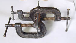
figure 120
When the filler has gone off unclamp the frames and mark each inlay (I use MO and PO with an arrow show the front). Using the end of a 1/6"drill bit pop the cast inlays out of each frame, remove the slight "burr" at the corners and with a sharp knife cut off the 2 pimples on the bottom of each inlay. Check that the edges of the castings have no air bubbles, if they have you will have to recast the inlay/s.
Figure 121 shows the frames unclamped and Figure 122 shows each inlay cleaned up etc.

figure 121
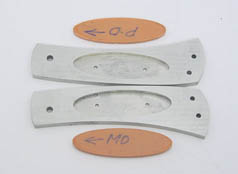
figure 122
Next step is to mount the castings and cut a dummy inlay.
I now take each casting and mount them on a backing plate (with superglue) that has had locating holes drilled in it from the template (I use aluminium although steel or even micarta will suffice as long as it is flat and parallel sided). I also use a pice of 1/8" micarta that has been drilled with locating holes, to mount my inlay material.
Figure 123 shows the 2 mounting plates and the piece of micarta used to mount the inlay material. NOTE the channel milled in the centre of the micarta. This is the approximate position the inlay material needs to be.
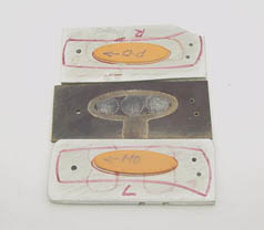
figure 123
Figure 124 shows the inlay master mounted on the bottom of the milling table and figure 125 shows the piece of micarta mounted on top of the table onto which I have stuck, with superglue, another piece of micarta that my dummy inlay will be cut from.
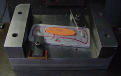
figure 124
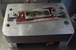
figure 125
Before I start to mill my inlays I replace the 3/16" carbide burr with a 1/8" end cutting carbide burr and also remove the 3/16' follower and replace it with a follower that I have turned down to 1/8" on the end. Because as I mentioned earlier all 3 jaw chuck have some runout the dummy inlay will by most accounts be smaller than the casting and I need to cut a larger inlay than my master. How much larger I never know until I do it. In order to do this I have turned a number of followers in .002" increments, starting with the 1/8" follower, up to around .135".
Figure 126 shows some of the followers.
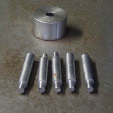
figure 126
I now proceed to cut the first dummy inlay. Figure 127 shows milling in progress.

figure 127
When I have cut this dummy I tap it off the mounting plate and try it for size in the appropriate frame. Figure 128 shows milling complete and Figure 129 shows the inlay in the frame.
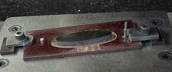
figure 128
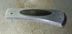
figure 129
9 times out of 10 it will be too small, so I replace the follower I've used with a larger one and repeat the process. I keep doing this until I reach the fit I want. It's up to the individual to decide how close a fit they need, however, bear in mind that any gap will be magnified by any fixative you use to hold the final inlay in place. I like to have mine fitting as close as humanly possible, almost like a piston when you insert them in the frame.
I will now cut dummies until I get the fit I want.
IMPORTANT NOTE: The way I've mounted my master inlay will cut an inlay that is a mirror image of it, therefore you must turn the cut inlay over. Always mark the inlay BEFORE you tap it off the backing plate. ie the top face of the cut inlay will be the INSIDE, therefore you must mount your final material inside out. I hope this is clear but if it isn't I will show you when I come to do my final inlay.
I am now ready to make my real inlay. I measure the depth of my cavity, 2.45mm (.100" approx.) against my inlay material, 2.00mm (.080"), which makes the inlay material thinner the the cavity depth, OK Inow stick some white "knifemakers paper" on the back of the inlay material which brings it up to 2.60mm leaving me approximately 0.15mm (.007") to grind off after fitting. I use loctite 324 speedbonder, a 2 part adhesive which sets in approximately 5 minutes, I also use this adhesive to glue the inlays in.
I mount the inlay material on my micarta plate with superglue and carefully mill out the inlay, I take cuts of 0.5mm (.020"). After milling out the inlay I mark the back for identification and alignment and then tap off the mounting plate. I then radius the bottom edge and polish the whole edge with 600 grit wet and dry.
Figure 130 shows my inlay material.
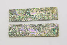
figure 130
Figure 131 shows the inlay milled out and the back marked, remember previously I mentioned that the inlay was mounted inside out, this demonstrates what I mean. The arrows indicated front and top and MI stands for markside inside.

figure 131
I now carefully try my inlay in the frame, it should be tight, but I should be able to press it in with my fingers. Hot dog, it fits spot on.
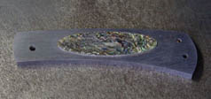
figure 132
I now remove inlay master from the bottom of the tap and replace it with the master of the other side, and on the top I turn the micarta mounting plate over and reclamp.
Theoretically the follower should be the same for both sides, but it's better to be sure than sorry, so I cut a dummy inlay for this side and check. Ok it's fine so I mount the inlay material and cut the second inlay, mark the back and remove from the mounting plate. Hooray this one fits fine also.
Figure 133 shows both inlays in their respective frames to gether with their dummy ones.
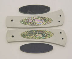
figure 133
OK that's the hard work done, now I will remove the inlays, file and polish the release cut-out, and relieve the inside of the frame.
I still have to grind the blade etc. so as I progress I will post the pictures.
I have now ground the blade, ladder pattern stainless damascus from Ed Van Hoy, heat treated, polished and etched it. I have also polished the bar, relieved, jewelled, shaped and polished the frame, and done the final fit up ready to assemble.
Figure 134 shows all the components ready for assembly.
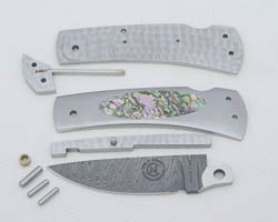
figure 134
I then assemble the piece, peen the pins, grind them off and repolish the knife. Before closing it I clean the internals with a degreaser, blow out the dust and add a drop of oil to the mechanism.
Figure 135 and 136 shows the finished piece. Now it's off to the engraver for some deep relief engraving and to think about a name for it. When it comes back I will post a picture.
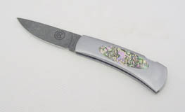
figure 135
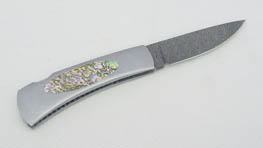
figure 136
Well that's it ladies and gentlemen, I hope you are all inspired and can hardly wait to build one, remember if you have any questions post them on the forum and I will do my best to answer them.
Regards from Australia.
Well it's all finished, Figure 137 shows it all engraved. I think it's come up looking great.
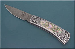
figure 137
Взято с knifenetwork.com

